We describe a new two-stage aerospace servovalve which has an additively manufactured titanium body, and a small piezoelectrically actuated spool as its pilot stage, with electrical main stage position feedback. The design approach promises to provide low weight, low leakage, and more accurate spool positioning. In addition, it enables increased manufacturing automation thereby reducing cost, increasing repeatability, and generates less waste material. Valve design, operation and measured performance are discussed below.
There are around 40 servovalves on a typical single-aisle airliner, being the key control component in both electrohydraulic actuation and fuel control systems. Reducing weight, manufacturing cost, and improving efficiency through reduced leakage are key drivers for new servovalve designs. If acceptable material properties can be obtained, producing servovalve bodies using additive manufacture (AM) could provide significant benefits in weight and manufacturing labour cost, as well as providing additional design freedom. Making complex internal flow galleries which have proven difficult using traditional manufacturing methods is straightforward with AM. It also allows new opportunities for integrating novel sensing and actuation within a valve.
A valve pilot stage refers to the torque motor and either nozzle-flapper, jet pipe or deflector jet amplifier, and provides the actuation to move the main spool (second stage). Torque motors can be time-consuming and expensive to set-up, requiring significant manual intervention. If not adjusted very precisely the pilot stage amplifier may not provide stable operation, and there is a continual flow loss (and power loss) through the nozzles or jet. An alternative approach is sought providing a more cost-effective, reliable, low leakage alternative which is amenable to automated manufacture.
The specific focus of this article is a new two-stage servovalve design incorporating piezoelectric actuation and electrical spool position feedback, manufactured using AM. To reduce leakage, a small spool is used for the pilot stage instead of a conventional nozzle-flapper, jet pipe or deflector jet amplifier.
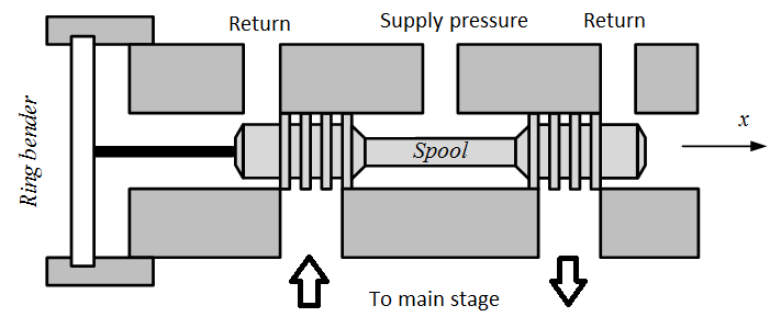
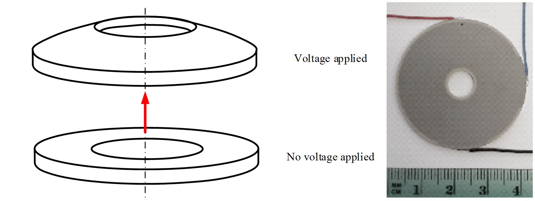
The valve pilot stage is a small spool that is directly driven by a piezoelectric ring bender (Figure 1). A ring bender is a flat annular disk that deforms in a concave or convex fashion depending on the polarity of the applied voltage. An example of the bending effect of the actuator can be seen in Figure 2. Such an actuator configuration has been chosen since a ring bender actuator exhibits a greater displacement than a stack actuator of the same mass, and an increase in stiffness in comparison to similar size rectangular bender (Bertin et al, 2014).
Figure 1. Pilot stage schematic
Figure 2. Piezoelecric ring bender: left - deformation, right - Noliac CMBR08 with electrical connections
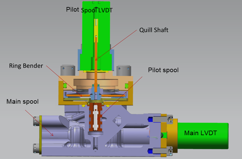
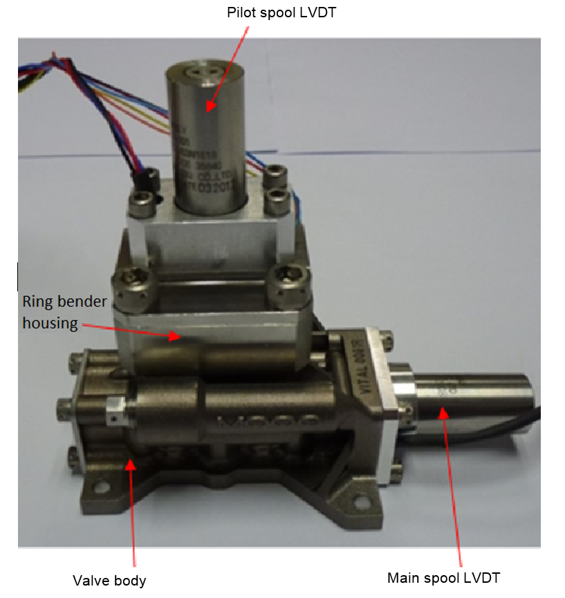
A Noliac CMBR08 multilayer ring bender is used in the valve. This has a 40mm diameter and 1.2mm thickness, a free displacement of ±115μm and a blocking force of ±39N. The ring bender is clamped in a flexible mount around its outer edge, and connected by a hub and shaft to the pilot stage spool. This is incorporated into the two-stage valve as shown in the cross-section of Figure 3. The completed valve is shown in Figure 4. The ring bender, which is submerged in hydraulic fluid, is attached to an LVDT to allow position monitoring during development. The main spool position is measured by a second LVDT enabling closed loop control; a proportional-integral position controller is used with compensation for non-linearities such as piezoelectric hysteresis, see Persson et al (2017) and Stefanski et al (2016).
Figure 3. Cross-section of valve design
Figure 4. Manufactured prototype valve
Additive Manufacture
Valve bodies contain intricate fluid galleries. They need to have the strength and stiffness to withstand high hydraulic pressures (e.g. 350bar), and maintain excellent dimensional accuracy despite pressure variations and large changes in temperature (-54°C to +150°C being a typical specification). Clearances around a spool, or tolerances on a metering edge, are of the order of a few microns. Metering edges are adjacent to high velocity fluid (frequently more than 100m/s) and are prone to erosive wear. Currently valve bodies are usually made from aluminium or titanium with a very hard wearing martensitic stainless steel (440C) bushing insert to form the metering edges.
Additive manufacture gives the opportunity to create complex valve bodies which are of much lower weight, only adding material where necessary, and are manufactured cost-effectively with high repeatability and low material waste. The geometry can be optimized to meet the stringent requirements outlined above, without the normal subtractive manufacturing constraints. Available AM processes are reviewed by (Frazier, 2014).
The valve prototype is manufactured from titanium alloy (Ti6Al4V) on a Renishaw AM250 machine which uses a powder bed fusion laser melting process. Laser melting is known to be successful with this material, although research is still required to ensure the characteristics and quality are suitable for aerospace applications. In particular, fatigue life is affected by surface finish and microstructure, and the effects of build process parameters and heat treatment are still being investigated (Tong et al, 2017). Certification questions arise with flight actuators and using additive manufacturing for safety critical parts requires new standards to be developed.
As described in (Guerrier, 2016), for servovalves and other complex hydraulic actuation components, application of AM promises a shorter development cycle, reduced inventory costs for material, better hydraulic efficiency, weight saving, and new repair opportunities.
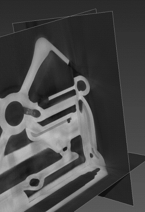
Figure 5 shows the AM valve body in more detail. A hard stainless steel bushing insert is still required to achieve the required wear properties for the metering edges. Figure 6 illustrates how internal inspection of AM parts can be achieved using CT scanning.
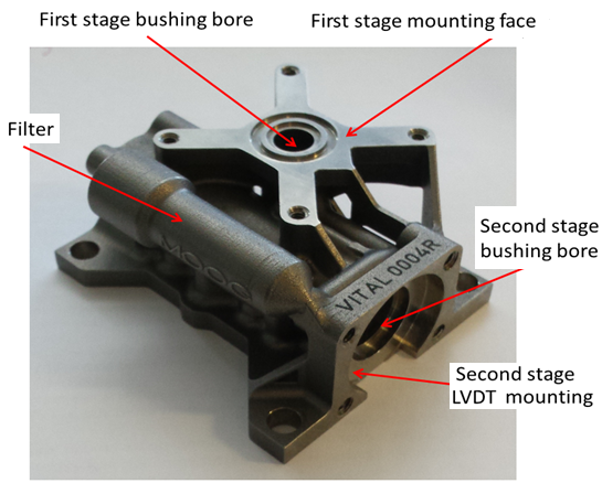
Figure 5 - AM body of initial prototype.
Figure 6 - Three-axis view of CT scan of AM valve body.
Measured Performance
Both static and dynamic valve performance have been tested. Statically, with 210bar supply pressure and connected cylinder ports, the maximum flow rate is just above 70 L/min, and the leakage flow from pressure to return in the closed (null) position is about 0.1 L/min.
Low frequency full scale cycling of the control signal shows that the ring bender hysteresis is about 20%, which is typical for piezoelectric actuators. However a similar test for the full range of main spool movement shows a linear relationship, as the closed loop controller successfully compensates for the ring bender hysteresis.
The dynamic response of the valve spool motion to the ring bender control signal is determined by: the power amplifier bandwidth and its current limit; damping, inertia and flow forces associated with the pilot stage motion; compressibility and flow restriction between the pilot and main stage; damping and flow forces acting on the main spool, along with its inertia, and the pressure difference from the pilot stage acting on the main spool end area. The factors affecting dynamic response are analysed in detail in Persson et al (2016) and Persson (2017).
Figure 7 is a frequency response measured from the final prototype, showing that the dynamic response is similar to conventional valves of the same size.
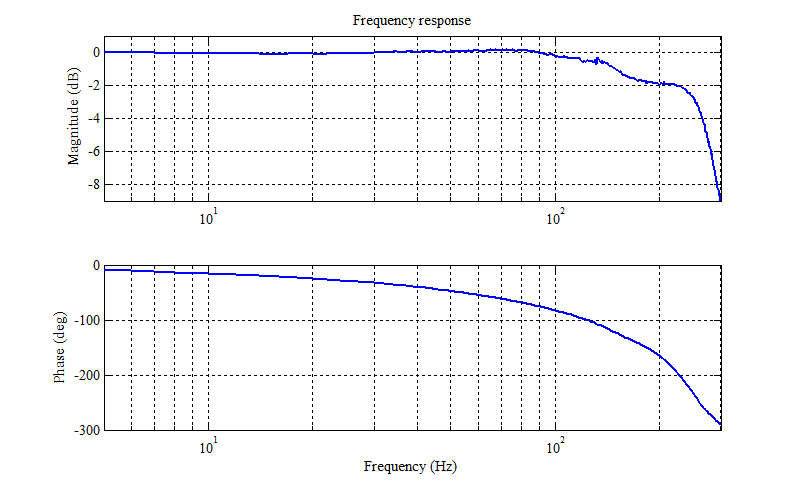
Figure 7 - Valve frequency response (210bar supply)
In Conclusion
A new aerospace servovalve has been prototyped, with a body manufactured by laser melting titanium powder (Ti6Al4V), and a low leakage piezoelectrically actuated pilot stage. Further development is required before commercialization, but the approach promises to provide:
- low weight and reduced size due to optimized AM structure,
- improved repeatability and reliability through eradication of fine-wire device (torque motor),
- better spool position control compared to conventional mechanical feedback valves: more precise, faster, less sensitive to environmental changes (e.g. temperature), less variability from one valve to another, with provision for ‘intelligent’ health monitoring,
- increased manufacturing automation, improving repeatability and reducing cost,
- manufacturing resource efficiency through less material waste,
- reduced pilot stage leakage, reducing power loss.
The functional requirements have been met. Durability requirements have also been verified through hydraulic and material fatigue testing, but additional research will be required before certification is possible. The use of electrical feedback is also a new departure for primary flight controls, and the safety case needs to be proven.
Further research is ongoing into protection and durability of piezoactuators operating in hydraulic fluid. Reducing the size of the piezo amplifier will also need to be addressed. Subtractive machining as a finishing operation for AM parts is necessary, and better integration of additive and subtractive processes is another research thrust.
References
- Bertin, M. J. F., Plummer A.R., Bowen C. R. Johnston D. N., (2014) An Investigation of Piezoelectric Ring Benders and their Potential for Actuating Servo Valves, Proceedings of the Bath/ASME symposium on fluid power and motion control, Sept 2014.
- Frazier, W. E. (2014), Metal additive manufacturing: A review, Journal of Materials Engineering and Performance, 23, 1917-1928.
- Guerrier, P., Zazynski, T., Gilson, E., Bowen, C. (2016) Additive Manufacturing for Next Generation Actuation. Recent Advances in Aerospace Actuation Systems and Components, Toulouse, March 2016.
- Persson, L., Plummer, A., Bowen, C. & Elliott, P. (2016) Dynamic Modelling and Performance of a Two Stage Piezoelectric Servovalve. Proceedings of the ASME 2016 9th FPNI Ph.D Symposium on Fluid Power, Brazil.
- Persson, L., Plummer, A., Bowen, C. & Elliott, P. (2017) Non-linear Control of a Piezoelectric Two Stage Servovalve. 15th Scandinavian International Conference on Fluid Power, Linkoping, June 2017.
- Persson, L.J. (2017) Design and Control of Piezoelectric Actuation for Hydraulic Valves. PhD Thesis, University of Bath.
- Stefanski, F., Minorowicza, B., Persson, L., Plummer, A., Bowen, C. (2016) Non-linear control of a hydraulic piezo-valve using a generalized Prandtl-Ishlinskii hysteresis model. Mechanical Systems and Signal Processing. vol. 82, pp. 412–431.
- Tong, J., C. Bowen, J. Persson, and A. Plummer, (2017) Mechanical Properties of titanium-based Ti – 6Al – 4V Alloys Manufactured by Powder Bed Additive Manufacture, Mater. Sci. Technol., 33, 2, p. 138-148
Acknowledgement
The authors would like to thank Innovate UK, Moog Aircraft Group and Renishaw plc for financial support and guidance during this work. We also acknowledge support of the University of Bath Impact Acceleration Account funded by the UK Engineering and Physical Sciences Research Council.