Main investigators:
Matteo Pellegri*, Prof. Andrea Vacca*.
*Maha Fluid Power Research Center, Purdue University
Contact: mpelleg@purdue.edu
Goal
This research focuses on the development of a simulation model that can be used to study the operation of Gerotor pumps and as a design tool for investigating new solutions. The model takes into account for the main fluid dynamics of the displacing process realized by the machine, considering also the mechanical interaction of the components, particularly as concerns the micro-motions of the rotors. The developed tool is capable of generating the geometry profiles or start from an existing CAD design of the rotors and simulate its operation within AMESim, predicting main features of the operation such as delivery pressure ripples, internal pressure peaks, rotor radial movements and torque losses.
Approach
Fig1. - Structure of the Gerotor Simulation Tool: interaction between the internal Modules and an external Hydraulic System.
The model is based on a multi domain simulation approach comprising sub-models for parametric geometry generation, numerical calculation of characteristic geometry data, fluid dynamic model and mechanical model (
Figure 1). A geometric generator of rotors based on the circular arc profile for the outer rotor was also created (
Figure 2). The simulation model, however, accepts any profile for the rotors.
Fig2. - Graphical user interface for the GEROTOR profile generator.
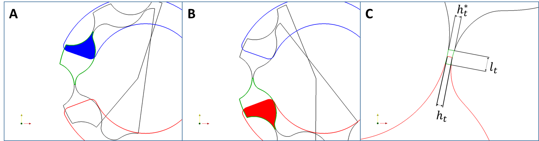
Once the geometry of the rotors has been defined, using the in-house Geometry Generator or a predefined profile are carried out, the C/C++ code evaluates the geometrical features of the pump. In particular, it evaluates the Displacement Chambers Volumes (DCV), the inlet and outlet areas (intersection between the DCV and the grooves as depicted in
Figure 3 and
Figure 4 A/B ) and the radial gap between the teeth of the inner and outer rotor along with the length of the gap (
Figure 4C).
Fig3. - Control Volumes and Intersection with Delivery (red) and Suction (blue) Ports.
Fig4. - (A/B) Area used by the Equivalent Orifice; (C) Tip Clearance and Equivalent Gap Length.
The fluid dynamic model evaluates the flow through the unit and it is the central part of the developed simulation procedure. In fact, the modeling equations and the assumptions made in it directly affect the implementation of the other sub-models, used to provide input data (
Figure 1) to the fluid dynamic model. The approach followed for this model is lumped parameters: the fluid domain is divided in control volumes in which fluid properties are assumed to be uniform. This approach is commonly used for studying the main flow features of hydrostatic units. In particular, each displacement chamber (Vi in
Figure 3), is considered as a separate control volume and its pressure is evaluated on the basis of the net flow entering or leaving it. The flow terms are evaluated with the turbulent orifice equation, to evaluate the flow between the DCVs and the suction and delivery ports, while the tooth tip leakages between adjacent DCVs have been accounted using laminar flow equations.

Fig5. - Projected DCV Areas for the Evaluation of Pressure Forces.
The simulation model also evaluates the pressure forces acting on each rotor. This is done by evaluating the single force components in each DCV in x and y axes. Thus, the surface corresponding to each tooth profile is projected on a plane perpendicular to the direction of the force, as shown in
Figure 4. The total force is then utilized in a journal bearing model to evaluate the actual position of the two rotors. This last information is used to carefully determine geometric parameters such as DCV volume, throat areas and the radial gaps. The micro motion evaluation plays a fundamental role on not only the prediction of the fluid dynamic features but also on the mechanical interaction between the rotors of the unit. The coupling of the mechanical module and the geometrical module of the current simulation model can be used as a valuable tool to estimate the correlation between the rotors profile geometry and factors responsible for the wear of the components namely contact pressure, sliding velocity and curvature of the profile putting the accent on the actual regions where contact occurs. The model is equipped also with a user-friendly post processing interface in which fluid properties inside of each control volume such as pressure, mass fraction of gas, and mechanical properties like tip clearance at the minimum distance between the rotors can be represented (
Figure 6).
Fig6. - Post Processing Add-in Interface.
Main results
Fig7. - (A) Comparison Between Measured and Simulated Delivery Pressure Ripple; (B) DCV Pressure
Over One Revolution of the Outer Rotor; (C) Comparison Between Experimental and Simulated
Characteristic Curves.
The model has been validated as concerns the prediction of the instantaneous flow oscillations (pressure ripple) and volumetric efficiency, and measurements were found to be in good accordance with the numerical predictions. At current stage, the model is capable of determining the influence of different designs of the gears or of the input/output port of the unit. Details on the internal flows as well as the instantaneous pressure inside the DCV can also be studied (Figure 7). The model is also capable of automatically identify the effect of geometrical tolerances and the region of contact resulting from the micro-motions of the two rotors (Figure 8). This omni-comprehensive model together with a computational efficient numerical approach, such as the lumped parameter, make the Gerotor simulation tool ideal for characterization and optimization of existing designs and for the study of new ones.
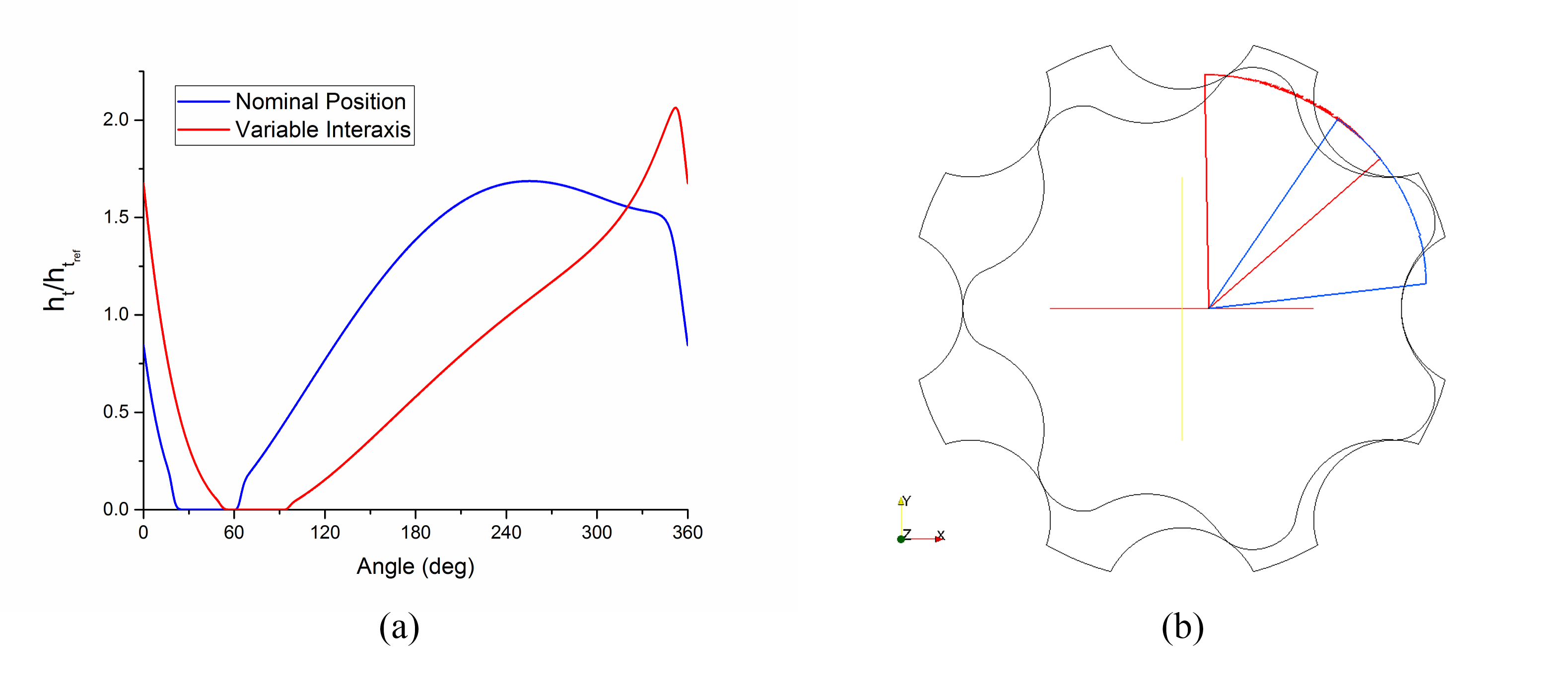
Fig8. - Example of numerical results from the simulation model (A) Tip Clearance Variation Over 1
Revolution of the outer rotor; (B) Arc of Contact for Two Different Interaxis Positions
Publications
- Pellegri, M., Vacca, A., 2016, Numerical simulation of Gerotor pumps considering rotor micro-motions, A. Meccanica, DOI: 10.1007/s11012-016-0536-6.
- Pellegri, M., Vacca, A., Frosina, E., Buono, D., Senatore, A., 2016, Numerical analysis and experimental validation of Gerotor pumps: A comparison between a lumped parameter and a computational fluid dynamics-based approach, Proceedings of the Institution of Mechanical Engineers, Part C: Journal of Mechanical Engineering Science, DOI: 10.1177/0954406216666874.
- Pellegri, M., Vacca, A., Devendran, R.S., Dautry, E., Ginsberg, B., 2016, A Lumped Parameter Approach for GEROTOR Pumps: Model Formulation and Experimental Validation, 10th Int. Fluid Power Conference, March 8-10, 2016, Dresden, Germany.
- Pellegri, M., Vacca, A., 2015, A CFD-Radial Motion Coupled Model for the Evaluation of the Features of Journal Bearings in External Gear Machines, ASME/Bath 2015 Symposium on Fluid Power and Motion Control, Oct 12-14, 2015, Chicago, IL, USA.